Autonomous Exploration in 3D environment
Planning, TARE global planner, Falco local planner
Collaborator(s): Atharva Patwe
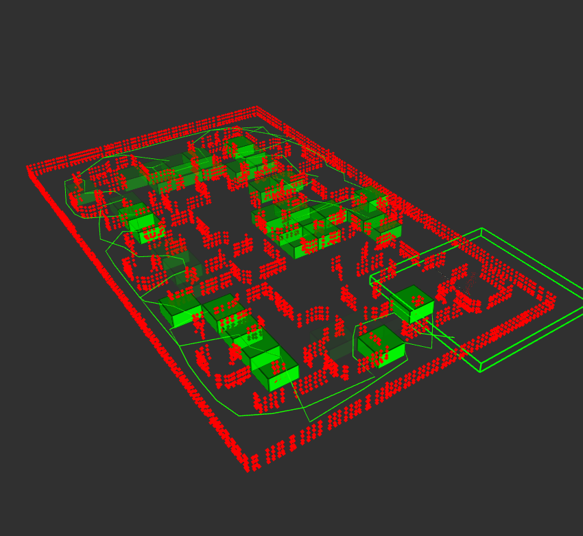
This project aims to deal with the autonomous exploration task in intricate three-dimensional (3D) environments to a turtlebot platform using onboard sensors - Depth Camera and Lidar. In terms of global planner, we use Technologies for Autonomous Robot Exploration (TARE) planner while we apply (Falco): Fast likelihood-based collision avoidance without a prior map for local planner, which were developed by CMU. In experiments, our systems autonomously explore environments at a high degree of complexity, with StoneFish simulator and Kobuki turtlebot robot.
Methodology
While implementing the mentioned methodology, two ROS nodes were developed. - Global Planner, Local Planner. The overall architecture is depicted in the figure below.

I. Lidar Plugin
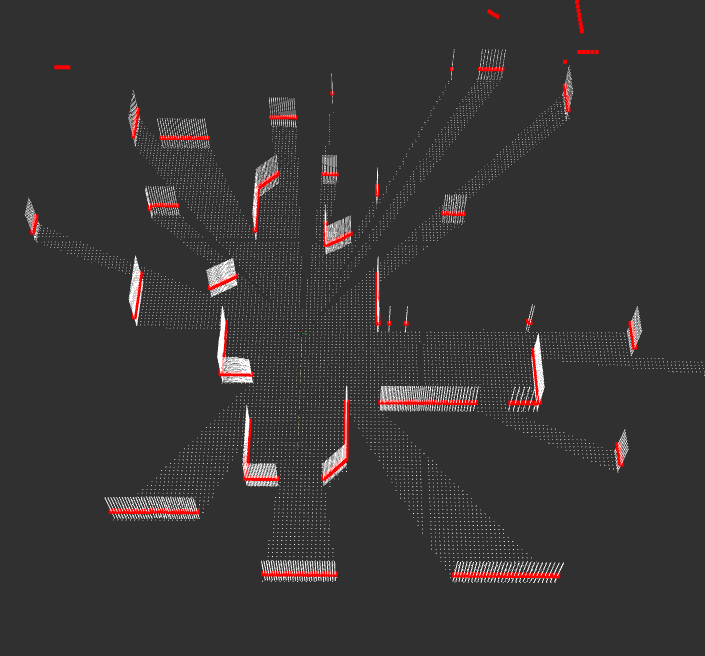
Initially, we intended to use a depth camera for the system to obtain a 3D point cloud. However, during development, we encountered problems synchronizing depth camera data and estimated state of the robot, so we decided to use lidar as a sensor for the system. Since lidar provides 2D data while the system evolves with 3D, we further developed this plugin, which helps convert lidar’s 2D data into 3D data. Basically, the plugin extends the obtained 2D point cloud in the Z direction to get elevation data. This is a situational solution, suitable for lab testing environments. Currently, we are still looking for a solution to synchronize depth camera data and robot status.

II. Global Planner
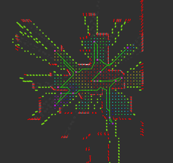
Global planner is calculated every 1 second and sends next way point to local planner. Output of the local planner is presented below is output of the glocbal planner.


III. Local Planner
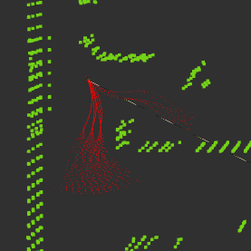
The path groups are pre-generated offline, and a voxel grid is used for collision checks. The correspondences between voxels and paths are pre-established and stored in an adjacency list. During operation, perception sensor data points are processed to label occluded paths. The algorithm then selects the path group with the highest probability $P(x_B|x_s)$. The computational complexity of the online processing algorithm is O(mnh), where m is the number of perception sensor data points, n is the number of paths in a path group, and h is the number of path groups. Result of the local planner is showed in Figure 10.

Results
Personal Contribution and Future Directions
My role in this project is to understand TARE and Falco planner as well as the package implemetation. From that, I applied these planners and package to StoneFish simulator, fine-tuned system parameters. The project provided me with a comprehensive knowledge in TARE path planning which utilizes a hierarchical framework to improve exploration efficiency. The experience honed my abilities in problem-solving, innovative thinking, and collaborative research, preparing me for a promising career in path planning for robotics.
The TARE planner works with a 3D omni-directional sensor such as 3D lidar. In terms of future direction, we are developing the planner working a depth camera. In order to deal with it, field of view, waypoints allocation strategy should be modified.